A reflow oven temperature profile records the actual temperature experienced by a PCB assembly as it passes through the oven.
The profile must match the solder paste specification, PCB thermal mass and component temperature limits. Oven zone settings alone cannot confirm the temperature of the solder joints.
The Four Reflow Profile Stages
Preheat
Preheat raises the PCB temperature gradually. Heating too quickly can cause solder-paste splatter, component stress and large temperature differences across the assembly.
Soak
The soak stage allows components with different thermal masses to reach a more consistent temperature before reflow. It also activates the solder-paste flux.
Reflow
The solder reaches its liquidus temperature, wets the pads and component terminations, and forms the solder joints.
Cooling
Controlled cooling solidifies the solder joints. Cooling that is too slow or too aggressive can affect solder structure, component stress and final joint quality.
Start with the Solder Paste Specification
The solder paste technical data sheet should define the recommended ramp rate, soak range, time above liquidus, peak temperature and cooling rate.
For many SAC lead-free solder pastes, an initial profile may use a gradual ramp, a soak around 150–180°C, approximately 45–90 seconds above the 217°C liquidus temperature and a peak near 235–245°C.
These are starting ranges, not universal settings. The final profile must stay within the solder paste and component limits.
Select the Correct Thermocouple Positions
Thermocouples should measure both the hottest and coldest areas of the PCB assembly.
Useful measurement points include a small passive component, a large connector, a power component, the centre of the PCB and a joint beneath or beside a high-thermal-mass package.
Attach each thermocouple directly to the measured solder joint or pad. A loose thermocouple or one touching only the component body can produce misleading results.
This requires testing and practice. For DEZ Reflow Oven customers, we will provide a comprehensive training system.
Create the Initial Oven Recipe
Set the first heating zones to raise the PCB temperature gradually. Use the middle zones to reduce temperature differences across the assembly and the final zones to bring every required solder joint above liquidus.
Conveyor speed determines how long the PCB remains in each stage. A slower speed increases heating time, while a faster speed reduces it.
Change one main variable at a time. Adjusting several zones and the conveyor speed together makes it difficult to identify which change improved or damaged the profile.
Run the PCB Through the Reflow Oven
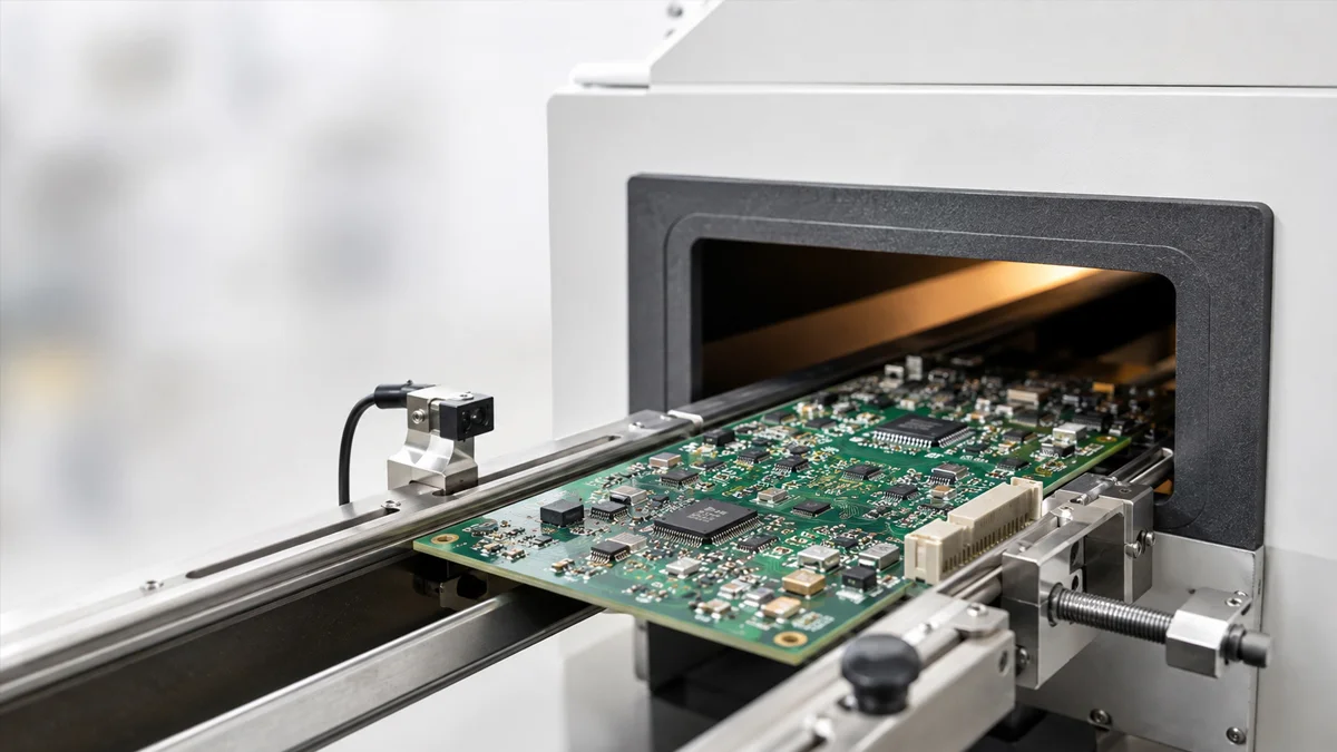
Connect the thermocouples to the temperature profiler and pass the instrumented PCB through the complete oven.
The recorded curves should confirm:
- Heating rate during preheat
- Temperature stability during soak
- Time above the solder liquidus
- Maximum temperature at each measurement point
- Temperature difference across the PCB
- Cooling rate after reflow
The coldest solder joint must reach the required reflow conditions without the hottest component exceeding its temperature limit.
Correct Common Profile Problems
The Coldest Joint Does Not Reach Reflow
Reduce the conveyor speed or increase the appropriate heating-zone temperatures. Check whether large connectors, shields, copper areas or PCB carriers are absorbing heat.
The Peak Temperature Is Too High
Lower the final heating zones or increase the conveyor speed. Confirm that small components are not heating much faster than high-thermal-mass areas.
The PCB Has a Large Temperature Difference
Extend or adjust the soak stage so that heavy and light components reach more similar temperatures before reflow.
Components Show Tombstoning
Check temperature balance across both component terminations. Pad design, solder-paste volume, placement and component geometry must also be inspected.
Solder Balls Appear After Reflow
Review the preheat ramp, solder-paste condition, printing process and PCB contamination. Temperature adjustment alone may not remove the cause.
Hidden Joints Show Voids
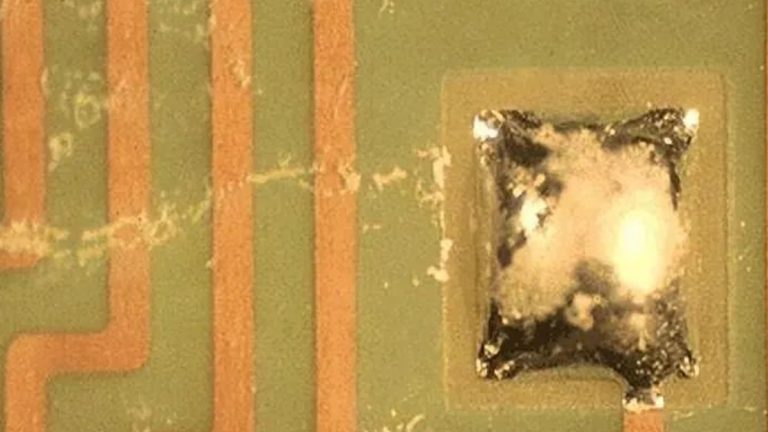
Review peak temperature, time above liquidus, soak conditions and cooling. Solder paste, pad design, component design and surface finish can also affect voiding.
Inspect the Solder Joints
A temperature curve must be confirmed against the finished PCB assembly.
Inspect visible joints for wetting, solder balls, bridging, disturbed joints and component movement. Use X-ray inspection for BGA, QFN, LGA and other packages with hidden solder connections.
One successful profile run is not enough. Repeat the process using several assemblies to confirm that the results remain stable.
Save a Profile for Each PCB Assembly
Different PCB models should not automatically share the same oven recipe.
PCB thickness, copper distribution, component size, board density, solder paste and carriers can change the heating response. Save the confirmed zone temperatures, conveyor speed and measured profile for each assembly.
Run a new profile when the PCB design, solder paste, component package, carrier, conveyor speed or oven condition changes.
Selecting a Reflow Oven
Provide the PCB dimensions, component height, solder paste, required throughput, conveyor direction and target temperature profile when selecting a reflow oven.
Assemblies with large connectors, shields, power components or heavy copper usually require more heating length and better temperature control than small, low-mass boards.
The DEZ-R800PC Reflow Oven uses eight upper and eight lower heating zones, a 3140 mm heating section, two cooling zones and three-channel temperature profiling.
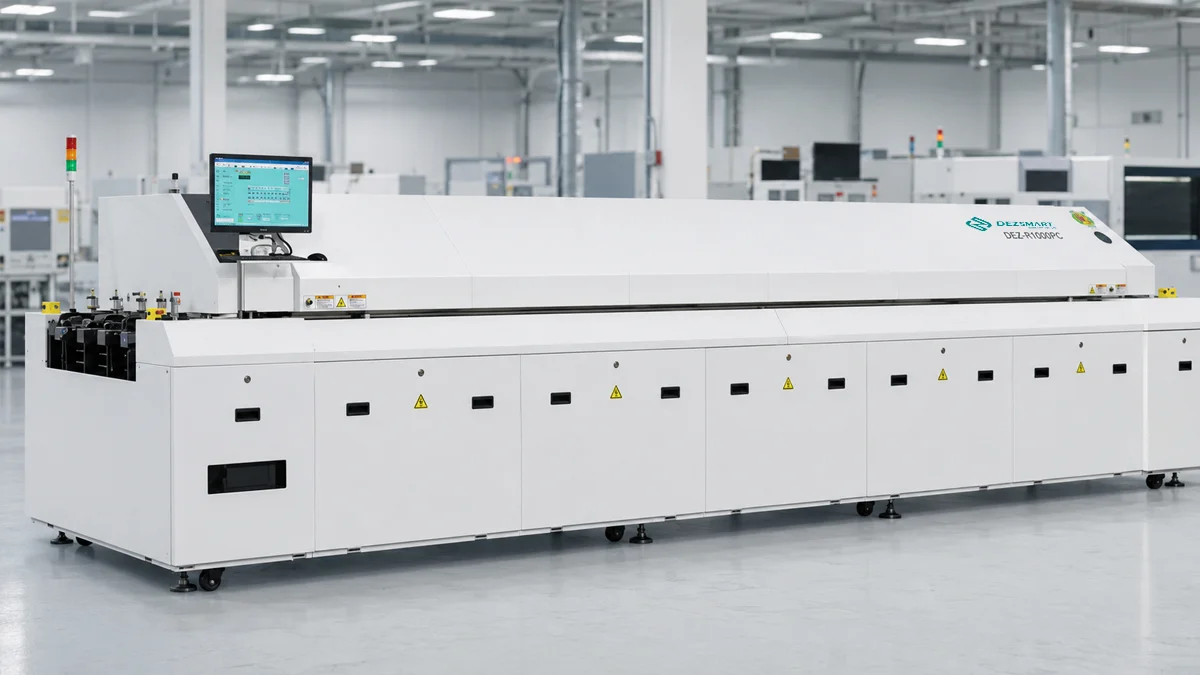
The DEZ-R1000PC SMT Reflow Oven provides ten upper and ten lower heating zones, a 3890 mm heating section, two cooling zones and three-channel temperature profiling.
Request Reflow Process Evaluation
Send your PCB dimensions, solder paste information, component layout, required throughput and target profile. DEZ can review the application and recommend the relevant reflow oven configuration.