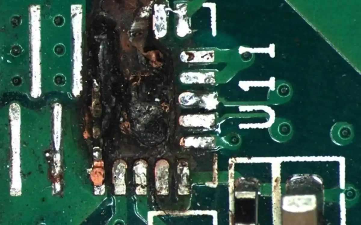
Flux residue on a PCB assembly is the material that remains after the flux in solder paste or separately applied liquid, gel or wire flux has performed its function during soldering.
Flux removes surface oxides, improves solder wetting and helps molten solder form a reliable joint. After reflow, wave soldering, selective soldering or hand soldering, part of the flux may evaporate or react, while resins, activators, salts and other reaction products can remain on the assembly.
In everyday search language, this is often called “flux residue on a PCB.” Technically, once components have been assembled and soldered, the workpiece is a PCBA.
Flux residue is not automatically a defect, and every PCBA does not automatically require cleaning. The decision depends on the flux chemistry, soldering process, assembly design, operating environment, electrical requirements, coating process and customer cleanliness specification.
Table of Contents
What Is Flux Residue Made Of?
The composition varies between solder pastes and liquid, gel or wire fluxes. Common residue constituents include:
Rosin, modified rosin or synthetic resin used as the film-forming material
Organic-acid activators and other chemicals used to remove metal oxides
Metal salts and reaction products formed during soldering
High-boiling carriers and additives that do not completely evaporate
Solder particles, dust and production contamination trapped in the residue
Cleaning-agent residue left by an incomplete cleaning or rinsing process
The residue may appear clear, amber, brown, white, sticky, powdery, glossy or glass-like. Appearance alone cannot determine whether it is electrically active, corrosive or acceptable.
Where Does Flux Residue Come From?
Reflow Soldering
Solder paste contains solder alloy particles and flux. During reflow, the flux activates, removes oxides and supports solder wetting. Resin and reaction products may remain around component leads, solder joints and underneath low-standoff packages.
Wave Soldering
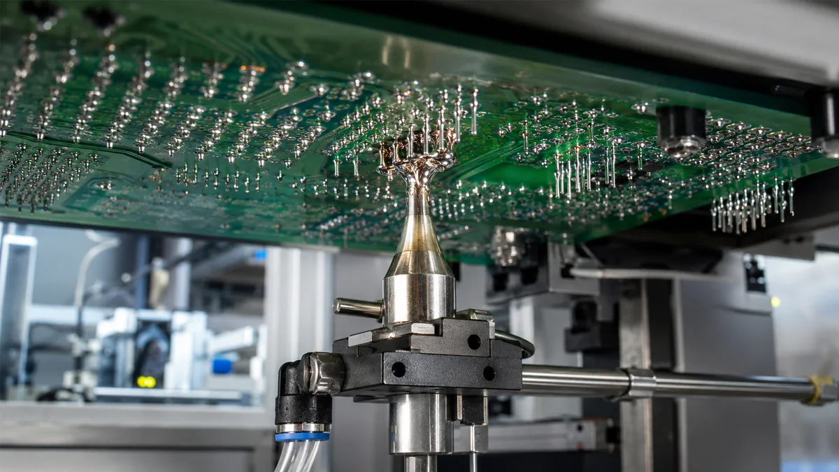
Liquid flux is applied to the solder side before the PCBA enters the preheating and solder-wave sections. Excessive flux, insufficient preheating or poor process control can leave visible residue across the solder side.
Selective Soldering
Selective soldering applies flux to programmed THT locations before preheating and mini-wave soldering. Residue may remain around connectors, terminals, relays and other through-hole joints.
Hand Soldering and Rework
Manual soldering and component rework can introduce concentrated residue around repaired joints. Repeated flux application and multiple heating cycles may make the remaining residue harder to remove.
Visible Flux Residue and Ionic Contamination Are Different
Visible flux residue is material that can be seen around solder joints or on the PCBA surface. Ionic contamination consists of mobile ionic species that may remain on the board even when it looks clean.
A visually clean PCBA can still contain measurable ionic contamination. A PCBA with visible resin residue may still meet a particular electrical cleanliness requirement.
The required result must therefore be defined before selecting a cleaning process.
Why Can Flux Residue Become a Problem?
Surface Insulation Resistance Reduction
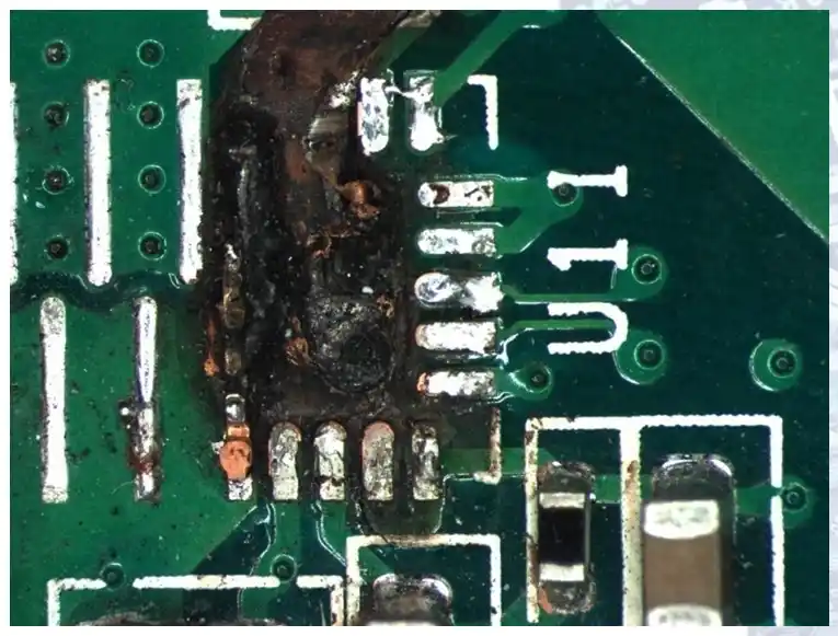
Moisture can interact with mobile ionic contamination and reduce surface insulation resistance between conductors. This can contribute to leakage current or unstable behaviour in high-impedance circuits.
Electrochemical Migration
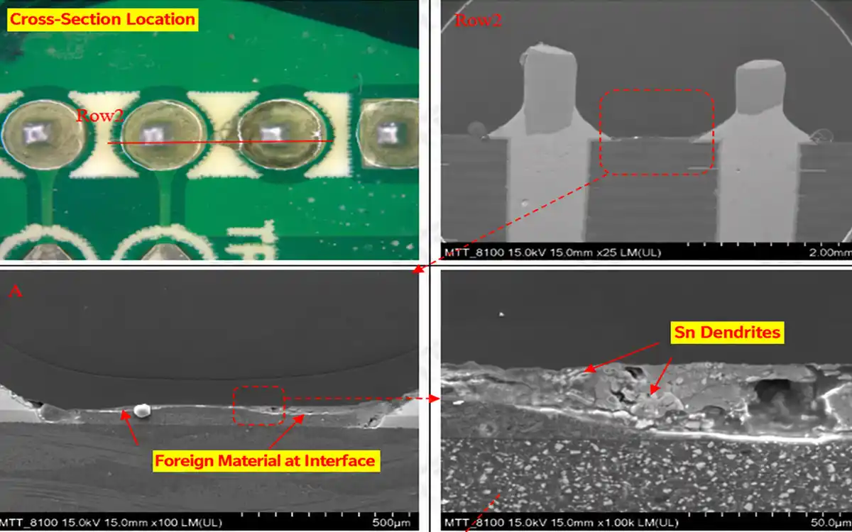
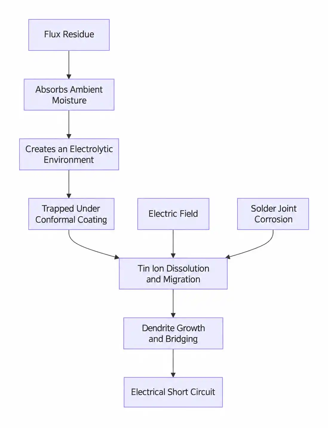
When moisture, ionic contamination and an electrical potential are present together, metal ions may migrate between conductors. Under suitable conditions, dendritic growth can develop and create an unintended conductive path.
Flux residue does not automatically cause electrochemical migration. The risk depends on residue chemistry, spacing, voltage, humidity, temperature and exposure time.
Corrosion
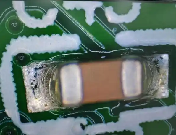
Aggressive or incompletely activated residue can contribute to corrosion of exposed conductors, component terminations or soldered connections. Residue trapped beneath low-standoff components can be particularly difficult to inspect and clean.
Conformal-Coating Problems
Contamination beneath conformal coating can interfere with coating adhesion, create uneven coverage or trap residue against the assembly.
A conformal coating should not be treated as a substitute for a qualified cleaning process. The PCBA surface condition must meet the coating supplier’s requirements before coating.
Flux on test pads can interfere with in-circuit test or functional-test probes. Residue may increase contact resistance, produce inconsistent readings or transfer onto the test fixture.
Inspection and Appearance
Dark or sticky residue can obstruct solder-joint inspection. White residue after cleaning may indicate incomplete removal, redeposition, incompatible chemistry, contaminated rinse water or reaction products.
Colour alone cannot confirm the cause. Flux type, cleaning chemistry, rinse-water quality and drying conditions must be reviewed together.
Which Flux Residues Must Be Removed?
Flux residue should be removed when the product specification, qualified manufacturing process or downstream operation requires a clean surface.
Typical conditions include:
Water-Soluble Flux Is Used
Water-soluble and organic-acid flux residues normally require a validated post-solder cleaning process. The cleaning interval and chemistry should follow the flux supplier’s technical requirements.
The PCBA Will Be Conformal Coated
Cleaning may be required when residue could affect coating adhesion, coverage or long-term behaviour. Compatibility testing should include the flux, cleaning process, coating and actual assembly materials.
The Circuit Has High Impedance or Small Conductor Spacing
High-impedance, high-voltage and fine-pitch circuits may require tighter ionic-contamination control because small leakage currents can affect operation.
The Assembly Operates in a Harsh Environment
PCBAs exposed to humidity, condensation, pollution, salt, temperature cycling or outdoor conditions may require cleaning and measurable process validation.
The industry name alone does not determine whether cleaning is necessary. The product environment and reliability requirement do.
Flux Was Not Fully Processed
Excessive flux, insufficient preheating, an unsuitable thermal profile or repeated rework can leave active or difficult-to-remove residue.
Cleaning the board does not correct an unstable soldering process. Flux volume, preheating and soldering parameters must also be corrected.
Residue Affects Testing, Bonding or Marking
Cleaning may be required before electrical probing, adhesive bonding, underfill, potting, labelling, marking or another surface-sensitive operation.
The Customer Specifies a Cleanliness Limit
Customer drawings and process specifications may define the cleaning method, test method, sampling frequency and acceptance limit. These requirements take priority over appearance alone.
How Do You Remove Flux Residue from a PCB Assembly?
There is no cleaning fluid or machine that removes every flux from every PCBA.
The most complete process is the one qualified for the actual flux chemistry, component materials, board geometry, production volume and required cleanliness result.
1. Identify the Flux and Residue
Record:
Solder-paste and liquid-flux product names
Flux classification and supplier cleaning guidance
Reflow, wave, selective or manual soldering process
Time between soldering and cleaning
Rework operations and additional flux
Contaminated areas
Component clearances and low-standoff packages
Fresh residue is often easier to remove than residue that has aged or passed through additional heating cycles.
2. Define the Required Result
Determine whether the process must achieve:
Removal of visible residue
Removal of loose solder balls and particles
Cleaning of one accessible solder side
Cleaning of both sides and areas beneath components
Preparation for conformal coating
A customer-defined ionic-contamination limit
A validated SIR or electrical-performance requirement
A machine selected only for visible brush cleaning should not be expected to perform complete aqueous washing and controlled DI-water rinsing.
3. Match the Cleaning Method to the Assembly
Single-Sided Brush Cleaning
Brush cleaning is suitable for accessible solder-side residue and loose solder balls after wave or selective soldering.
It is not intended to wash the complete assembly, reach every area beneath components or provide a controlled DI-water rinse.
Offline Batch Aqueous Cleaning
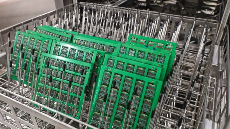
Offline batch cleaning processes multiple compatible PCBAs in a basket. A qualified process can combine chemical spray washing, DI-water rinsing and hot-air drying.
This format is suitable for high-mix production, frequent product changes and factories that do not require a continuously connected cleaning line.
Inline Aqueous Cleaning
Inline aqueous cleaning continuously transfers PCBAs through chemical washing, DI-water rinsing and hot-air drying.
It is suitable for repeated products and production volumes that justify continuous conveyorised processing.
Manual Cleaning
Manual cleaning can be used for local rework and low-volume tasks. However, simply dissolving flux with IPA and allowing the liquid to evaporate may spread dissolved contamination and redeposit it elsewhere.
A controlled manual process must use compatible chemistry, clean tools, extraction with lint-free absorbent material and adequate drying.
Ultrasonic Cleaning
Ultrasonic cleaning should not be applied to populated assemblies without confirming component and material compatibility. MEMS devices, microphones, crystals, sensors, transformers, coils, piezoelectric components and trapped-liquid areas may require special evaluation.
4. Wash, Rinse and Dry as Separate Functions
The main cleaning agent dissolves or removes the compatible flux residue.
DI water is used after washing to remove dissolved contamination and remaining cleaning agent. DI water is not automatically the primary flux-removal chemistry.
The drying stage must remove moisture from component gaps, connectors and other retention areas. A surface that feels dry may still retain liquid beneath low-standoff components.
5. Test Actual PCBAs
Before final machine selection, process boards carrying the actual flux residue. Evaluate:
Supports PCBA widths of 50–300 mm and component heights up to 135 mm. Adjustable conveyor speed is 0.05–1.8 m/min. A Ø100 mm application roller applies cleaner before multidirectional wet brushing, dry brushing and fan drying.
Automatic brush cleaning for PCBAs up to 300 × 300 mm
Processes an accessible solder-side surface. Requires a board edge of at least 1.5 mm. Uses an alcohol-based PCBA cleaning fluid, a 360 mm rotary brush and two roller brushes. Conveyor speed is adjustable from 0.05 to 1.8 m/min.
High-mix offline cleaning with complete washing, rinsing and drying
Uses a double-layer 610 × 560 × 100 mm basket with a maximum 10 kg batch load. The process is heated spray washing, DI-water rinsing and hot-air drying. Wash temperature is 25–75°C, maximum drying temperature is 99°C and required DI-water resistivity is more than 15 MΩ·cm.
Continuous aqueous cleaning after reflow, wave or selective soldering
Supports product widths of 50–500 mm on a 500 mm SUS316 mesh conveyor. Conveyor speed is adjustable up to 1000 mm/min. It performs chemical washing, DI-water rinsing and two-zone hot-air drying. Required DI-water resistivity is above 15 MΩ·cm.
Fixed workstation for local PCBA flux and rework-residue cleaning
Cleans exposed solder joints, component leads, connectors and repaired areas. Adjustable pressure is 0.1–0.8 MPa, dry ice feed is 0.1–0.6 kg/min and hopper capacity is 5–10 kg. The floor-standing system includes extraction for loosened contamination.
Repetitive waterless cleaning integrated into production
Supports a maximum cleaning area of 400 × 350 mm. Dry ice feed is adjustable from 0.1 to 0.6 kg/min, with adjustable pressure of 0.1–0.8 MPa. The enclosed system requires no water rinse or hot-air drying stage.
The PCB cleaning machine category covers dry particle removal from bare PCBs before printing. Flux residue after soldering requires equipment from the PCBA cleaning category. Current DEZ product specifications confirm these different process boundaries.
How Do You Test Whether Flux Residue Is Acceptable?
A flux-residue result is acceptable only when it meets a defined requirement.
There is no universal visual appearance or single ionic number that proves every PCBA is suitable for every application.
Visual Inspection
Visual inspection can identify:
Visible flux marks
White residue
Sticky surfaces
Loose solder balls
Residue on test pads
Residue around connectors or component leads
Incomplete drying
Visual inspection cannot prove that ionic contamination has been removed.
ROSE Testing
ROSE stands for Resistivity of Solvent Extract. The method extracts ionisable contamination from the assembly and reports a bulk result, commonly expressed as a sodium-chloride equivalent.
ROSE is useful for monitoring whether a qualified production process remains within its established control limits. It does not identify individual ionic species or show their exact location.
IPC-TM-650 Method 2.3.25D explicitly describes ROSE as a process-control tool and states that it does not predict reliability.
Ion Chromatography
Ion chromatography can identify and quantify specific ionic species extracted from the assembly. It is useful for investigating the source of contamination and comparing cleaning-process results.
The extraction location and method matter. A whole-board result may not reveal a concentrated residue pocket beneath a particular low-standoff component.
Surface Insulation Resistance Testing
SIR testing evaluates electrical resistance under defined temperature, humidity and bias conditions. It can support validation of a flux, soldering and cleaning process where electrical reliability is the main concern.
SIR is not interchangeable with a visual inspection or a bulk ionic test.
Coating and Electrical Verification
Depending on the product, additional checks may include:
Conformal-coating adhesion
Electrical functional testing
In-circuit testing
Leakage-current measurement
Insulation-resistance testing
Inspection after environmental conditioning
Cleanliness testing before and after the cleaning process
Why Does White Residue Appear After Cleaning?
Possible causes include:
Flux that is only partially dissolved
Incompatible cleaning chemistry
Contaminated IPA or cleaning liquid
Evaporation without removing dissolved contamination
Insufficient DI-water rinsing
Hard-water minerals
Cleaning-agent residue
Reaction products created during soldering or cleaning
Residue trapped beneath components and released during drying
Changing to a stronger cleaner without compatibility testing can damage markings, plastics, coatings, adhesives or other assembly materials.
The correct investigation compares the original flux, cleaning-agent concentration, wash temperature, mechanical action, rinse-water quality, drying process and residue location.
Practical PCBA Cleaning Qualification
A repeatable qualification should use actual production PCBAs carrying representative residue.
Step 1: Record the Process
Document the flux, solder alloy, soldering method, thermal profile, residue age, board dimensions, component layout and required cleanliness result.
Step 2: Establish the Uncleaned Baseline
Inspect and test representative uncleaned assemblies. Record visible residue and the selected cleanliness measurements.
Step 3: Run Sample Cleaning
Test the proposed brush, batch or inline process using compatible chemistry and controlled parameters.
Step 4: Verify Cleaning and Material Compatibility
Check accessible surfaces, areas beneath components, connectors, markings, plastics, labels and any coating or bonding surfaces.
Step 5: Confirm Rinsing and Drying
Evaluate rinse-water quality, cleaning-agent carryover, trapped liquid and residue that appears after drying.
Step 6: Set the Production Window
Define the approved chemistry concentration, temperature, time, spray or brush settings, rinse-water requirement, drying settings, bath-maintenance limits and testing frequency.
Frequently Asked Questions
Is flux residue electrically conductive?
Some residues contain mobile ionic material that can contribute to leakage when moisture and electrical bias are present.
Does no-clean flux cause corrosion?
Properly selected and processed no-clean flux may remain on qualified assemblies. Risk increases when too much flux is applied, the residue is not fully heat-activated, moisture is present or the product operates outside the qualified conditions.
Can IPA completely remove flux residue?
IPA can dissolve some fluxes but is not effective for every formulation. If contaminated IPA evaporates on the board, dissolved residue may be redistributed rather than removed. Confirm the cleaning agent with the flux supplier and validate the complete removal and drying process.
Can DI water alone remove flux?
DI water can remove compatible water-soluble contamination, but it does not dissolve every rosin, resin or no-clean residue. Many aqueous processes require a compatible cleaning agent followed by DI-water rinsing.
How soon should PCBAs be cleaned after soldering?
Clean within the qualified process interval. Residue that has aged, hardened or passed through additional thermal cycles may require more time, temperature or chemical action.
Can the DEZ-C753S remove flux residue?
No. The DEZ-C753S is a dry double-sided cleaning machine for dust, fibres and loose particles on bare PCBs before solder paste printing.
Discuss Your Flux-Residue Cleaning Process
DEZ can evaluate whether the application requires accessible dry ice cleaning, offline batch aqueous cleaning or continuous inline cleaning.