When Does a THT Assembly Need Selective Soldering?
When mixed SMT and THT assemblies require selective soldering, when wave or manual soldering remains suitable, and how to select the correct DEZ machine.
A THT assembly needs selective soldering when only defined through-hole joints require solder, while reflowed SMD components, contact areas or other protected regions on the solder side must remain outside a full solder wave.
The decision is therefore not determined simply by whether a PCB contains THT components. It depends on solder-side access, component clearances, board thermal demand, production mix and the number of joints that must be processed.
Table of Contents
When Can a THT Assembly Use Wave Soldering Instead of Selective Soldering?
Consider a mixed-technology PCBA that has already completed solder paste printing, component placement and reflow. Connectors, transformers, relays or other THT components are then inserted for a secondary soldering process.
If most of the underside is clear and nearly every THT joint can be soldered together, conventional wave soldering may still be the more efficient choice. A properly designed wave-soldering pallet can protect selected areas when sufficient clearance is available.
The situation changes when the solder side contains reflowed SMD components, gold contacts, board-edge interfaces, test points or densely packed no-solder areas. A full wave would expose too much of the assembly, while a complicated pallet could restrict solder flow or become expensive to maintain across frequent product changes.
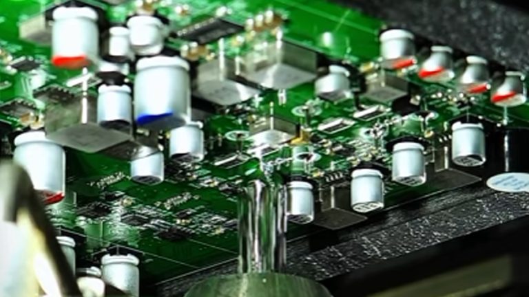
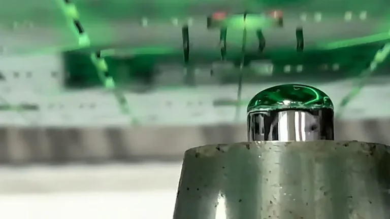
Selective soldering solves this by applying flux only to programmed locations, preheating the required area and moving a nitrogen-protected mini-wave nozzle beneath specified THT joints. The process controls where solder reaches the board instead of exposing the entire underside.
There is no universal component-clearance value that automatically decides between wave and selective soldering. Nozzle access depends on the selected nozzle, component height, lead projection, pallet design and keep-out geometry. These conditions must be checked from the actual PCB or carrier drawing.
When Is Selective Soldering the Better Choice for THT Assembly?
The most common trigger is a mixed SMT/THT board with bottom-side components close to the through-hole joints. However, component density alone is not the whole reason.
Selective soldering also becomes practical when a manufacturer needs repeatable flux volume, preheat and solder-contact parameters across multiple product variants. A programmed process reduces the operator dependence associated with hand soldering and avoids making a different masking pallet for every suitable board revision.
This does not mean selective soldering is limited to low-volume production. A compact offline machine can support prototype and high-mix work, while multi-station inline systems can process fluxing, preheating and soldering in parallel for continuous production. Selective soldering equipment is used across batch, high-mix and higher-volume manufacturing when board design and process control justify it.
Thermal demand is equally important. Thick multilayer boards, heavy copper planes and large connectors can draw heat away from the barrel and make through-hole fill difficult. In this case, selective soldering is useful only when the machine provides enough controlled preheat and solder contact for the actual assembly. Increasing solder-contact time without understanding the thermal load can overheat the local area while still failing to achieve consistent barrel fill.
PCB design also affects the result. Pad geometry, thermal relief, lead-to-hole relationship and nozzle access can determine whether the process window is stable. Selective soldering cannot compensate indefinitely for a joint that is physically inaccessible or thermally unbalanced. IPC technical work on selective soldering likewise highlights the relationship between board design, accessibility and process performance.
When Is Selective Soldering Not the Best Option?
For a prototype with only one or two accessible THT joints, controlled hand soldering may be faster than programming a machine. At the opposite extreme, a high-volume board with a clear solder side and widely distributed THT joints may be processed more efficiently by conventional wave soldering.
High reliability by itself does not make selective soldering mandatory. The equipment is justified when local process control, protected solder-side areas, repeatable production or product-change requirements make wave soldering or manual soldering unsuitable.
The comparison must use the real cycle time. Joint count alone is insufficient because the program can include fluxing movements, preheat time, nozzle travel, individual points and drag-soldering paths. A board with many adjacent connector pins may process efficiently by drag soldering, while scattered joints can require considerably more nozzle travel.
How to Choose the Right DEZ Selective Soldering Machine
DEZ provides offline and inline configurations for different board sizes, thermal requirements and production methods. The machine should be selected only after confirming the usable soldering area, not merely the external PCB dimensions.
Production condition
Suitable DEZ machine
Relevant capability
Small PCB, development work or low-volume production with limited preheat demand
Three parallel stations for fluxing, preheating and soldering; carrier size up to 500 × 600 mm and soldering area up to 500 × 450 mm
These specifications establish the basic size and production boundaries. They do not replace a soldering evaluation. A smaller machine is not automatically suitable merely because the bare PCB fits inside it; clamps, carriers, nozzle clearance and component overhang can reduce the accessible soldering area.
How Does BGA Affect the THT Selective Soldering Process?
A mixed-technology assembly may contain both BGA packages and THT connectors, but the two component types do not use the same soldering process. BGAs are normally attached during SMT reflow. Selective soldering is then used for the specified through-hole joints added later.
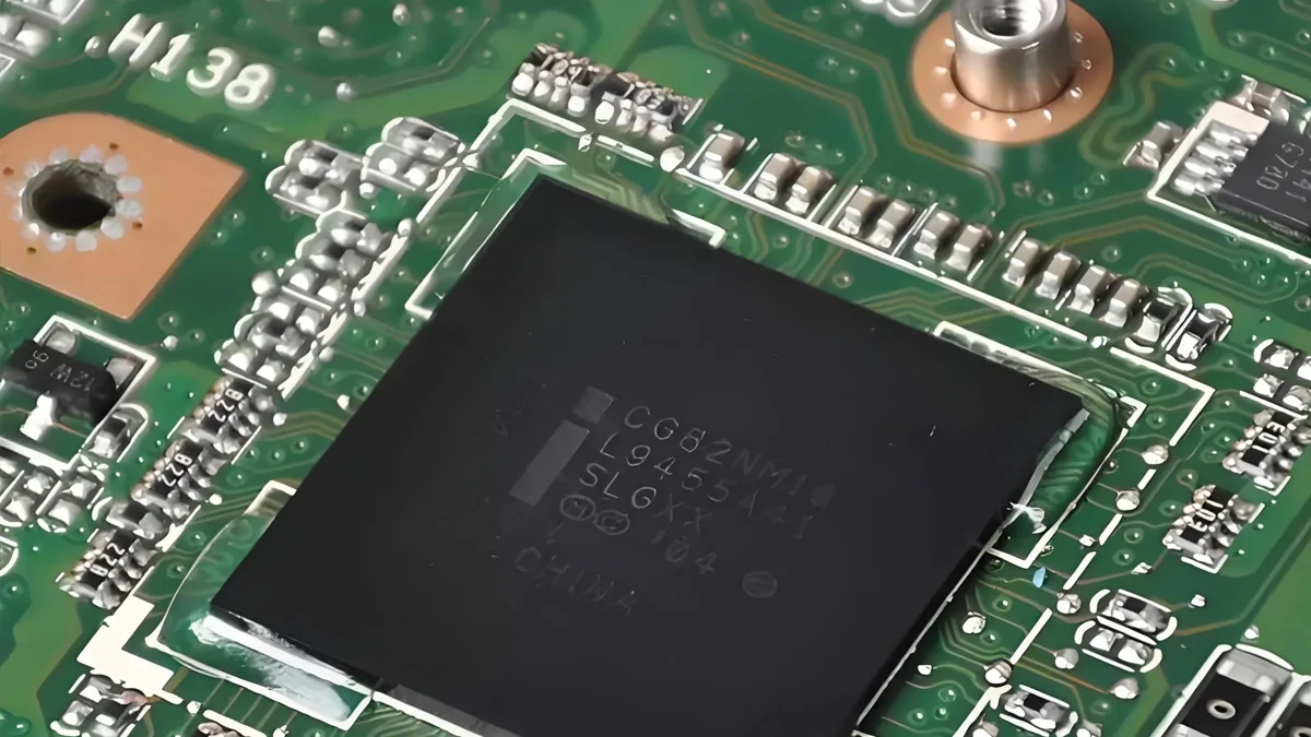
If the concern is voiding, bridging, opens or insufficient solder beneath a BGA, the correct process is non-destructive X-ray inspection rather than selective soldering. The DEZ-X7600 PCBA X-Ray Inspection System is intended for examining hidden solder-joint structures. When a confirmed BGA defect requires component removal and replacement, the appropriate equipment is a BGA rework station.
What Information Is Needed to Select a Selective Soldering Machine?
The correct selection starts with the PCB or carrier drawing, marked THT coordinates and solder-side keep-out areas. DEZ also needs the board thickness, copper or thermal-mass information, solder alloy, flux, required barrel fill, planned takt time, nitrogen availability, transfer direction and line height.
These details show whether the assembly should remain with manual soldering, use conventional wave soldering or move to a programmed selective process. They also determine the required nozzle access, preheating configuration and machine capacity.