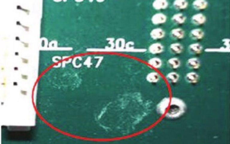
Ionic contamination is soluble charged material remaining on a PCB or PCBA after fabrication, soldering, handling or cleaning. It may include chloride, bromide, sodium, potassium, sulphate, nitrate and organic-acid ions.
These contaminants are often present at concentrations that cannot be seen. When moisture dissolves them, they can increase surface conductivity and contribute to leakage, corrosion or electrochemical migration under electrical bias.
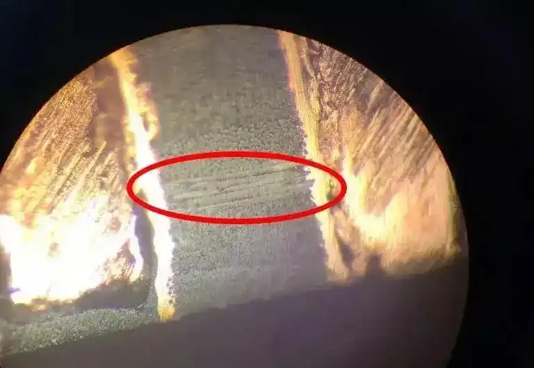
Visible residue describes what can be seen rather than how it behaves chemically. Flux films, white deposits, dust, fibres, fingerprints, oils and solder balls are all visible residue, but they are not automatically ionic or non-ionic.
Ionic Contamination vs Visible Residue
Comparison
Ionic contamination
Visible residue
Definition
Soluble charged species on the assembly
Contamination detected visually or under magnification
Visibility
Frequently invisible
Visible directly, by camera or under a microscope
Examples
Chloride, bromide, sodium, potassium and organic-acid ions
Flux films, white deposits, fibres, oils, dust and solder balls
Electrical behaviour
Can increase conductivity when dissolved in moisture
Depends on composition; it may be conductive, insulating or contain ions
Main concern
Leakage, corrosion and electrochemical migration
Appearance, inspection, contact, coating, bonding or particle-related problems
Verification
ROSE, ion chromatography, SIR or another defined test
Visual or optical inspection
Visible residue should not be described as harmless merely because it appears non-metallic. Flux films and fingerprints may contain ionic material, while metal particles and solder balls may create electrical risks without being measured as ionic contamination.
How Ionic Contamination Becomes an Electrical Risk
Ionic contamination does not automatically produce a short circuit. The risk develops through the interaction of contamination, moisture, electrical bias, conductor spacing and time.
When moisture forms a thin film on the assembly, soluble ions enter the liquid and increase its conductivity. This can reduce surface insulation resistance and create leakage between conductors.
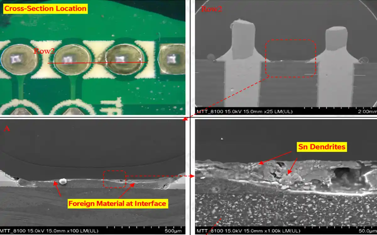
Under continuing electrical bias, metal may dissolve at one conductor, migrate through the electrolyte and deposit elsewhere. This electrochemical migration can form dendrites and eventually create an unintended conductive path.
A contaminated assembly may therefore pass dry factory testing but behave differently after exposure to humidity, condensation or temperature cycling.
Where Ionic Contamination Comes From
The likely source depends on when the contamination appears.
Process stage
Possible source
What to check
Bare-board fabrication
Etching, plating, surface finishing or insufficient rinsing
Supplier process data and incoming-board cleanliness
Reflow soldering
Solder-paste activators and reaction products
Paste type, applied volume and thermal profile
Wave or selective soldering
Liquid flux, excessive application or insufficient preheating
Flux quantity, spray pattern, preheat and soldering parameters
Manual soldering or rework
Locally applied flux and repeated heating
Flux product, application method and number of rework cycles
Cleaning and rinsing
Contaminated wash solution, cleaner carryover or poor rinse water
Chemistry concentration, bath condition and DI-water quality
Handling
Fingerprints and perspiration
Gloves, handling method and exposed test areas
Drying and storage
Trapped moisture or environmental contamination
Drying result, packaging and storage conditions
How Is Ionic Contamination Detected?
The test method should be selected according to the question that must be answered.
Method
What it tells you
Main limitation
Visual inspection
Whether accessible residue, particles, water marks or corrosion are visible
Cannot prove ionic cleanliness
ROSE
The bulk level of extractable ionic contamination
Does not identify individual ions or their location
Ion chromatography
Which ionic species are present and their measured quantities
Result depends on the extraction area and procedure
SIR
How a representative process behaves under defined humidity, temperature and electrical bias
Does not identify the specific contaminant
Localised extraction
Whether a particular component or process area contains concentrated contamination
Does not represent the complete assembly unless sampling is planned correctly
What Is an Acceptable Ionic-Contamination Level?
There is no universal value that proves every assembly is reliable.
A valid acceptance requirement must define the test method, extraction conditions, calculated surface area, units, sampling plan and pass/fail limit.
The historical value of 1.56 µg NaCl equivalent/cm² should not automatically be used as a universal qualification limit. IPC removed it as the default basis for qualifying a manufacturing process when IPC J-STD-001H was introduced.
The applicable limit should come from the customer specification, product requirement or qualified manufacturing process.
How Should the Cleaning Process Be Selected?
The first decision is whether the requirement concerns visible residue, ionic contamination or both.
Visible Residue on an Accessible Surface
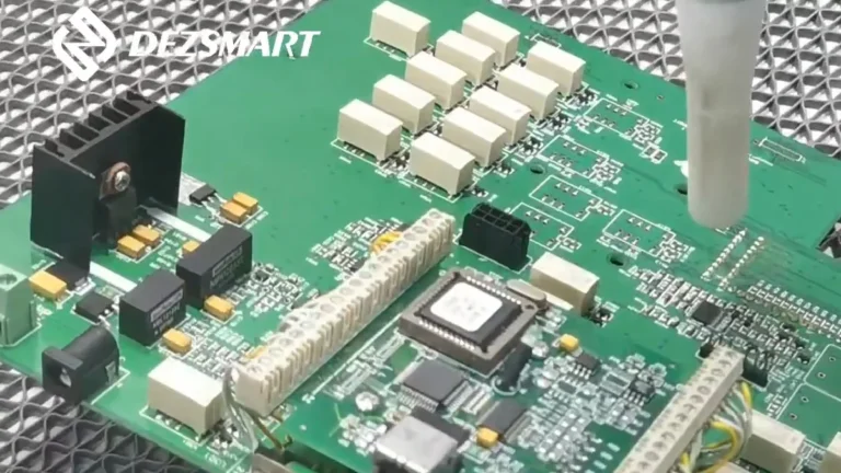
Brush or dry ice cleaning may be suitable when the main requirement is to remove accessible flux marks, solder balls or local rework residue.
DEZ dry ice cleaning machines provide waterless cleaning for compatible exposed flux and rework residue. The range includes the fixed-station DEZ-C7310, inline DEZ-C7320 and portable DEZ-C1650.
These processes can remove residue containing ionic material, but visible removal does not prove that an ionic-cleanliness limit has been achieved.
Ionic Contamination Requiring Full Washing and Rinsing
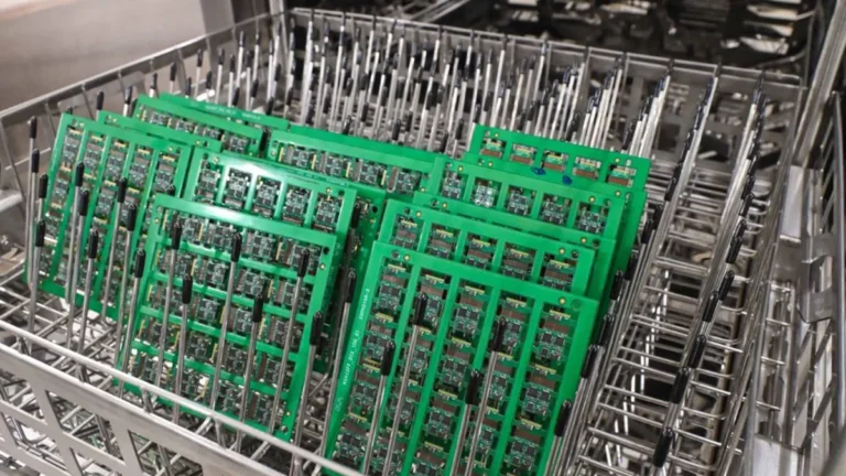
When the complete assembly requires chemical washing, DI-water rinsing and controlled drying, use a validated aqueous process.
The main sequence is:
Compatible Chemical Wash → DI-Water Rinse → Controlled Drying → Cleanliness Test
The cleaning chemistry performs the main washing action. DI water removes dissolved contamination and remaining cleaning agent after washing.
DI water should not be described as the primary flux-cleaning stage.
Start with representative assemblies carrying actual production contamination. Record the flux, soldering process, residue location, cleaning chemistry and current test result.
Clean the samples using controlled parameters, then repeat the same inspection and ionic test. This establishes whether the process removes the target contamination instead of merely improving appearance.
For aqueous cleaning, confirm wash chemistry, DI-water quality, rinse effectiveness and drying. For brush or dry ice cleaning, confirm access to the contaminated area and test ionic cleanliness separately when required.
Once the result is acceptable, define the process settings, bath-maintenance limits, sampling frequency and conditions that require requalification.
Frequently Asked Questions
Does visible flux residue mean ionic contamination is too high?
Not necessarily. Appearance cannot determine the type or quantity of ionic contamination. Test the assembly against the specified requirement.
Does passing ROSE prove reliability?
No. ROSE is a process-control method. Product qualification may also require ion chromatography, SIR, electrical testing or environmental evaluation.
Can DI water alone remove all ionic contamination?
No. Some contamination is trapped inside flux or other residue and first requires a compatible cleaning agent. DI water is then used to rinse away dissolved contamination and remaining cleaner.
Can dry ice cleaning remove ionic contamination?
Dry ice can remove accessible residue containing ionic material, but it does not provide a complete dissolution and DI-water rinsing process. Test the cleaned assembly when ionic cleanliness is specified.
Evaluate Your Cleaning Process
Send DEZ representative samples, residue photographs, flux information, cleaning-process data and the required test method.
DEZ can evaluate whether the application requires accessible brush cleaning, local dry ice cleaning, offline batch aqueous cleaning or continuous inline aqueous cleaning.